LinkedIn

LinkedIn
Click the image to view Author Linked In Profile

Saturday, 30 January 2021


Must-Have Tools and Techniques for Project Managers in 2021


Introduction
Of course, there are many project management tools and techniques, and they vary among organizations. The tools and techniques discussed in this article are the ones I use, and I would be lost without them. It is important to always be on the cutting edge of project management, and I want to avoid anyone deriding me as a dinosaur project manager from the 80s or 90s.

It is a lot of work to stay current. My organization uses a vendor-provided, web-based application for our dashboard and project plans. This vendor provides emails with new trends in project management and free webinars. I get recordings of these webinars, too.

That is my main method of staying current. Like any industry, you stay current by reading the latest information, attending webinars, and collaborating with colleagues to avoid silos. Project managers must decide which tools and techniques apply to their organization and industry. I want to re-emphasize the following ones. 

Must-Have Tools and Techniques for Project Managers in 2021

1. A project manager must have a dashboard exclusively for project management. It is standard procedure and your top project management tool. Dashboards provide a quick health check of your projects. They are also a visual representation of your projects, and a picture is worth a thousand words. Dashboards should provide the status of each project and links to other information and key performance indicators (KPIs), like return on investment, earned value, customer satisfaction, cost variance, and so forth.

Management likes dashboards since they save time. You will get fewer calls from colleagues asking about the project’s status. Benefits include more collaboration, better decision making, and more agreement on status/next steps. Some of your colleagues will remember your dashboard more than almost anything else about you as a project manager. (Is that a good thing?) Ensure your dashboard is web based and that everyone else knows about it. Remember, like the project plan, always keep your dashboard presentable, updated, and instantly accessible. Make it eye-catching, with pleasing colors and significant bling (see Figure 1).

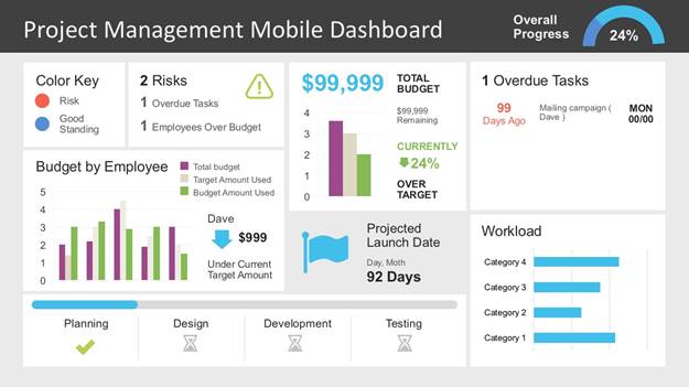
Figure 1: Project management mobile dashboard (SlideModel, 2020)

2. Do no be afraid of project plans. Some project managers do not like project plans. I cannot tell you how many vendors send me project plans and that is the last I ever hear about them. I get a project plan and the vendor never sends an updated one. Schedule a project status teleconference and always insist on updating the project plan to reflect the status. Avoid taking shortcuts, instead try to embrace the less desirable aspects of your job. Do not let vendors off the hook about keeping the project plan current.

Some project managers will do whatever is necessary to avoid using a project plan. Try not to be afraid of them. Break project plans into sections with subsections using colors, so the project plan is eye-catching. Try to avoid line after line of tasks in the execution phase. Instead, group similar tasks, like testing and training, by subphases. I know: Some project managers use other tools besides project plans, especially for agile. But I have not found anything superior to project plans.

I have seen many project plans without predecessors/dependencies—some project managers are afraid of them, but they are the glue that keeps the timelines in sync. Here is a refresher: finish to start (FS), start to start (SS), finish to finish (FF), and start to finish (SF). Again, use dependencies to determine the task order. The task that comes before is the predecessor. The task that comes after is the successor. You can have multiple predecessors for one successor task or a single predecessor for multiple successor tasks. Include Gantt charts since they are a good visualization for project manager presentations to the stakeholders—stakeholders often prefer viewing them instead of just lines of tasks in the project plan. The project owner is busy and consults that Gantt chart as a quick reference. Nothing makes a stakeholder’s eyes glaze over more than looking at endless lines of tasks in a project plan (see Figure 2).

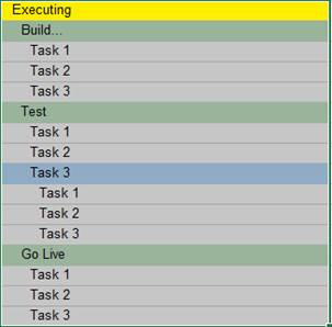
Figure 2: Task list (Boyer, 2020)

3. There is always a project charter, even if it is just an outline in an email. Sometimes it is a work order in your tracking system. But somebody must tell you what they want, when they want it, the project goals/outcome, budget, and so on. Spend as much time as necessary refining it until there is stakeholder agreement. Expect a fair amount of back and forth until you have a final project charter that clearly details all aspects of the project. Avoid just accepting whatever someone puts in front of you. Be proactive and polite.

4. An organization chart is important to help understand job titles and reporting relationships among stakeholders. I have seen project managers run projects without knowing who reports to whom, and that is a problem when resolving project issues. A project manager must know who can help resolve an issue with just a quick glance at an organization chart—and not waste time trying to figure it out when the clock is ticking.

5. Another useful project management tool is being proactive. Yes, project managers should be among the most proactive members in any organization. But after years at the same organization, a project manager can get stuck in a rut and slow down. Again, over time, you just seem to do the same thing every day and lull into inattention when you should always be trying to improve. Ask yourself every day if you are doing everything you can to be proactive. Take 10 minutes of your day to review each project and ask yourself whether you have done everything possible to make this project a success. Ask yourself, “Have I overlooked anything?”

6. Schedule a recurring meeting/teleconference with the project owner. It is amazing what people do not tell you unless you ask them. It is important to schedule a one-on-one meeting with the project owner to discuss the project status. Again, it is amazing what stakeholders will tell you one on one. Schedule that meeting with the project owner as soon as possible. Again, be proactive and polite.

7. Include swim lanes in your flowchart to visualize how the finished product will work. Again, a picture is worth a thousand words. The project manager or business analyst should provide a flowchart to visualize what is going to happen and when—and who or what is responsible for the action. Also, number each task in action in the flowchart. Stakeholders appreciate numbers to indicate the start/end and sequence of actions in a flowchart. No flowchart is complete without swim lanes and a number sequence (see Figure 3). Of course, a lot of my colleagues are visual and want to see a picture of how the project should work, and flowcharts provide it. Several times, a flowchart expedites a sign-off on the project charter instead of more delays and less time to complete an important project.

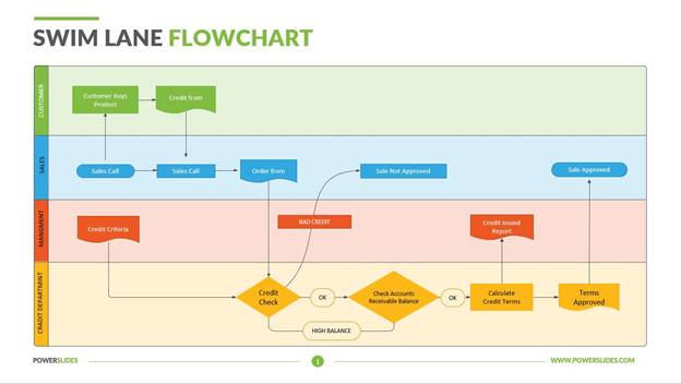
Figure 3: Swim lane flowchart (PowerSlides, 2020)

8. Insist on accountability. There is nothing more frustrating than constantly extending the start/finish dates of tasks because a stakeholder is too busy to finish them. Too many organizations allow stakeholders to delay tasks without any consequences. Stakeholders should use overtime to complete tasks. I know: Some stakeholders will look at you like you have lost your mind if you suggest overtime. Follow up with management as necessary and emphasize the impact to the schedule without the use of overtime.

9. Manage requirements. That is critical. If the requirements are not top notch, then it is all downhill from there. Schedule that requirements teleconference with the stakeholders and review the requirements. Do not trust stakeholders to thoroughly review the requirements on their own. Again, schedule that teleconference. Ensure that you review the requirements with the business analyst prior to that requirements meeting with stakeholders. Also, review the test cases with the quality assurance analyst.

10. Watch scope creep. Project managers often overlook asking stakeholders to break projects into phases. Of course, first deliver the most essential functionality, then the next essential functionality, and so on. Avoid being just an order taker and provide an updated budget and project completion date due to the impact from the scope creep/change request.

11. A project manager must have an issue log. Send it with the project status report. Again, work on the issues in the log. Do not just send it and forget it. It is crucial to resolve issues now instead of 5 minutes before a project status meeting. Schedule quick meetings with stakeholders who can help you resolve issues. Always send a meeting invite if you must meet with the stakeholder later instead of now. Again, send that meeting invite; otherwise, the stakeholder will forget and then there is another delay in resolving an issue. Remember, your stakeholders are your most valuable assets. Be brief and quick to the point, especially with executives.

Do not hesitate to ask for their help. Be respectful of stakeholders’ time. Check a stakeholder’s calendar to see when they are available. Do not phone stakeholders when they are in meetings unless it is an emergency. A project manager should use every opportunity to collect mobile phone numbers from stakeholders and vendors. A stakeholder’s or vendor’s desk number is of no value to me. I want mobile phone numbers. You can possibly find them in your company directory, but ask if necessary.

12. Send those project status reports, but then immediately follow up with a phone call or in person to discuss how to get the project back on track. Avoid just sending these reports and hoping a report recipient fixes the problem. Status reports (see Figure 4) are especially useful to show stakeholders that something must be done now to fix an issue, like being over budget or behind schedule. Yes, project status reports are useless if you just send them and do not follow up. Once more, be proactive and polite.

Include earned value in your project status report, and everyone will be impressed.

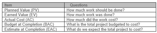
Figure 4: Sample project status report (Reichel, 2006)

Honorable Mentions

  1. Build a cheat sheet of lessons learned/postmortem. Read it to avoid previous issues with new projects, include a list of dos and don’ts from previous projects. Ensure you list the basic items you need for every project and refer to that list for every new project.
  2. Use lists, lists, and more lists to prioritize projects.
  3. Watch for signs that the stakeholders no longer value the project. After months of executing a project, sometimes stakeholders no longer see value or never saw enough value from the beginning. Remember, terminate a project as soon as possible if it no longer makes sense to the stakeholders.
  4. Conduct anonymous end-of-project surveys—this is scary. It is amazing what stakeholders will divulge in anonymity instead of directly to you. Implement their recommendations.
  5. Add a RACI (responsible, accountable, consulted, informed) chart to your organization chart. Again, it is important to know as much as possible about your stakeholders.
  6. Use agile for sprints to complete deliverable units of work, typically every 2 weeks. Ensure that everyone on the project team attends status meetings to discuss accomplishments for today and accomplishments for tomorrow.
  7. Also, use Kanban for simpler projects. It is just three columns on a board with “To Do,” “Doing,” and “Done.” Move tasks from one column to another as you complete them. There is project management software for it, too.
  8. Keep up with emerging trends:
    • Greater reliance on digital and remote teams;
    • A closer connection between projects and strategy;
    • Project management and change management;
    • The emergence of hybrid project management approaches;
    • An emphasis on soft skills; and
    • The impact of artificial intelligence and data analytics (Stobierski, 2020).
  9. Evaluate your organization’s capacity for change:
    • Understand the change saturation/overload condition. Organizations today risk overcommitting resources, resulting in an overload condition and inability to cope.
    • Prevent overload. Balance your organization’s portfolio of programs and projects to achieve critical results.
    • Build change capacity. Build a roadmap for organizational project management that aligns project management practices with business strategies (Harrington, 2014).

Saturday, 2 July 2016

PUBLISHED ARTICLE BY THE BLOG AUTHOR


PLEASE FIND THE LINKS BELOW TO SEE THE ONLINE PUBLISHED BY THE BLOG AUTHOR ON ISSUE.COM.

https://issuu.com/sivasubbiah/docs/wind_turbine_power/1?e=18561198/30000297

https://issuu.com/sivasubbiah/docs/solar_power_project

https://issuu.com/sivasubbiah/docs/project_management

just copy paste the link to learn about articles related to Project Management, Solar & Wind Turbine project. 

Thursday, 30 June 2016

ROLES AND RESPONSIBILITIES OF A PLANNING ENGINEER


A planning engineer has one of the most important roles in construction projects. Planning Engineers are responsible for ensuring that the project will be completed as per project management plan deadlines. He should raise any potential risks before it happens and guide the whole team through the project different stages. 

1. FIELD KNOWLEDGE 

Strong construction background required to understanding the scope of the project and identify the activities and activities dependency. This experience could be gained by working as a Site Engineer for a period of time or by monitoring and observing the work progress.

2. SOFTWARE SKILLS 

He should be familiar with project management terms and techniques such as EVM (Earned Value Management), CPM (Critical Path Method) etc, as PMP (Project Management Professional Certificate) will cover this point.  He should know how to process the planning techniques via software and produce visual aids to help explain the schedule of work. Primavera, MS Project, MS Excel are essential, which are used in the market now.

3. ATTENTION TO DETAILS 

Accuracy is the main core of Planning Engineers works. The main difference between successful planning engineer and another engineer is to pay attention to details, engineering common sense , data analysis and filtration. Planning engineers are dealing with the big amount of data every day. However, they should figure out what this data try to say and not just pass them to others.

4. COMMUNICATION AND INTERPERSONAL SKILLS

Planning Engineers are a key player in a construction project. They communicate almost with the whole project team, attend variance meetings with different parties and prepare a lot of reports. Therefore Good communication and interpersonal skills are required.

5. RESPONSIBILITIES

Simply the planning engineer should prepare a plan to complete the works on time and within budget. This plan cannot be done by planning engineer only. However, the planning engineer responsibility is to coordinate with all project team and collect pieces of information from different parties and put them all together on one workable project management plan.

Ø  Understanding the scope of the project

Ø  Identifying the best series of events in the correct order for the project to finish on time and on a budget.

Ø  Presenting the schedule of work to others in the company and the client organization involved with the project.

Ø  Developing detailed yet simple to understand schedule and graphs
Ø  Providing visual aids to help explain the schedule of work, including bar charts and network diagrams.
Ø  Using specialized computer software to help keep the project on course.

Ø  Monitoring the progress of the project at different stages of its development.

Ø  Making sure the achieved progress on the project fits the progress anticipated in the schedule.
Ø  Keeping in contact with the project manager.

Ø  Making adjustment to schedules if necessary.

Ø  Liaising with individuals on the project .

Ø  Ensuring that all the separate elements of the project fit together and working towards a correct direction.


Thursday, 10 March 2016

Difference b/w Architect and Civil Engineer

Civil engineering and architecture are similar, overlapping majors and occupations, with some key differences.

Architecture

Build public or private structures.Focus on the aesthetic principles of design. In school, you will take more art-related classes and fewer engineering- and science-related courses.Acquire the relevant certifications in the field of architecture.

Engineering

Build public or private structures, with a focus on public structures.Also build hydroelectric dams, canals, roadways, or other structures with useful functions in society.Focus on science and engineering. In college, you will take fewer art-related classes and learn a lot more engineering and physics than you would if you majored in architecture. This major is usually considered more “difficult.”Acquire the relevant certifications in the field of civil engineering.

As you can see, there is a large crossover in what you can do with either degree. As an architect or a civil engineer, you can build public or private structures. Civil engineers typically do a lot more work on large public ventures like airports however than they do on private homes. But that doesn’t mean a civil engineer can’t also build a house.

Architects cannot do everything that civil engineers can do, since they lack the scientific and engineering knowledge required for many jobs. An architect can build a house or even an airport, but probably will not be given the job of designing a power dam or a roadway for example. Those jobs require more technical knowledge and planning, and architecture school doesn’t really give you that knowledge since it is focused more on aesthetics.

Civil engineering’s main drawback is that it is a longer, more challenging pathway, and if you have no interest in technical projects, it would be more logical to avoid doing all that extra work just so you can build houses. Architecture isn’t offered as often as civil engineering however, so you may have an easier time finding a civil engineering course than an architecture course. So in summary, civil engineering is a broader degree field which allows you to do more types of projects after you graduate, but architecture is a more direct route if you already know you want to focus on more aesthetic projects. Talking to an advisor will help you figure out what you should do, but hopefully this gives you some starting guidance.

Self Consolidation Concrete

Self-consolidating concrete or self-compacting concrete

(SCC) is characterized by a low yield stress, high deformability, and moderate viscosity necessary to ensure uniform suspension of solid particles during transportation, placement (without external compaction), and thereafter until the concrete sets.

Such concrete can be used for casting heavily reinforced sections, places where there can be no access to vibrators for compaction and in complex shapes of formwork which may otherwise be impossible to cast, giving a far superior surface than conventional concrete. SCC was conceptualized in 1986 by Prof. Okamura at Ouchi University, Japan.

The first generation of SCC used in North America was characterized by the use of relatively high content of binder as well as high dosages of chemicals admixtures, usually superplasticizer to enhance flowability and stability. Such high-performance concrete had been used mostly in repair applications and for casting concrete in restricted areas. The first generation of SCC was therefore characterized and specified for specialized applications.

The relatively high cost of material used in such concrete continues to hinder its widespread use in various segments of theconstruction industry, including commercial construction, however the productivity economics take over in achieving favorable performance benefits and works out to be economical in pre-cast industry. The incorporation of powder, including supplementary cementitious materials and filler, can increase the volume of the paste, hence enhancing deformability, and can also increase the cohesiveness of the paste and stability of the concrete. The reduction incement content and increase in packing density of materials finer than 80 µm, like fly ash etc. can reduce the water-cement ratio, and the high-range water reducer (HRWR) demand. The reduction in free water can reduce the concentration of viscosity-enhancing admixture (VEA) necessary to ensure proper stability during casting and thereafter until the onset of hardening. It has been demonstrated that a total sand content of about 50% of total aggregate is favorable in designing for SCC.

Wednesday, 9 March 2016

Electrical Tower Transmission

Electrical Transmission Tower Types and Design

The main supporting unit of overhead transmission line is transmission tower. Transmission towers have to carry the heavy transmission conductor at a sufficient safe height from ground. In addition to that all towers have to sustain all kinds of natural calamities. So transmission tower designing is an important engineering job where all three basic engineering concepts, civil, mechanical and electrical engineering concepts are equally applicable.

A power transmission tower consists of the following parts, 1) Peak of transmission tower 2) Cross arm of transmission tower 3) Boom of transmission tower 4) Cage of transmission tower 5) Transmission Tower Body 6) Leg of transmission tower 7) Stub/Anchor Bolt and Base plate assembly of transmission tower. The main parts among these are shown in the pictures.

Peak of Transmission Tower

The portion above the top cross arm is called peak of transmission tower. Generally earth shield wire connected to the tip of this peak.

Cross Arm of Transmission Tower

Cross arms of transmission tower hold the transmission conductor. The dimension of cross arm depends on the level of transmission voltage, configuration and minimum forming angle for stress distribution.

Cage of Transmission Tower

The portion between tower body and peak is known as cage of transmission tower. This portion of the tower holds the cross arms.

Transmission Tower Body

The portion from bottom cross arms up to the ground level is called transmission tower body. This portion of the tower plays a vital role for maintaining required ground clearance of the bottom conductor of the transmission line.

Design of Transmission Tower

During design of transmission tower the following points to be considered in mind, a) The minimum ground clearance of the lowest conductor point above the ground level. b) The length of the insulator string. c) The minimum clearance to be maintained between conductors and between conductor and tower. d) The location of ground wire with respect to outer most conductors. e) The mid span clearance required from considerations of the dynamic behavior of conductor and lightening protection of the line. To determine the actual transmission tower height by considering the above points, we have divided the total height of tower in four parts, 1. Minimum permissible ground clearance (H1) 2. Maximum sag of the conductor (H2) 3. Vertical spacing between top and bottom conductors (H3) 4. Vertical clearance between ground wire and top conductor (H4).

Types of Transmission Tower

According to different considerations, there are different types of transmission towers. The transmission line goes as per available corridors. Due to unavailability of shortest distance straight corridor transmission line has to deviate from its straight way when obstruction comes. In total length of a long transmission line there may be several deviation points. According to the angle of deviation there are four types of transmission tower- 1. A – type tower – angle of deviation 0o to 2o. 2. B – type tower – angle of deviation 2o to 15o. 3. C – type tower – angle of deviation 15o to 30o. 4. D – type tower – angle of deviation 30o to 60o.

As per the force applied by the conductor on the cross arms, the transmission towers can be categorized in another way- 1. Tangent suspension tower and it is generally A - type tower.

2. Angle tower or tension tower or sometime it is called section tower. All B, C and D types of transmission towers come under this category.

Apart from the above customized type of tower, the tower is designed to meet special usages listed below,

These are called special type tower

1. River crossing tower

2. Railway/ Highway crossing tower

3. Transposition tower

Based on numbers of circuits carried by a transmission tower, it can be classisfied as- 1. Single circuit tower

2. Double circuit tower

3. Multi circuit tower.

Saturday, 16 January 2016

Intermediate Transition Zone (ITZ) in concrete

What is ITZ and how it is developed in concrete

ITZ in civil engineering terminology is known as interfacial transition zone or intermediate transition zone. This is the phase present in concrete where two different phases meet with each other. As you can see in the picture you can see clearly the layer of ITZ presence 

In concrete aggregate is considered as one phase and surrounding paste is considered as another. For concrete to bear load, it is imperative that there should be stress distribution between paste and aggregate.

When these two phases of concrete meet, there is always an ITZ layer present. This layer has properties which are neither of aggregate phase nor to the paste phase.

What happens is when that near aggregate slurry (water+cement) accumulates causing a layer which is shown in picture below. This layer is week because of its chemical composition.

Strength

In reality, ITZ has probably the lowest strength properties therefore under loadsstress in aggregate phase will be different than that of the paste for same strain level. This type of non-uniform stressdistribution will cause ineffective transmission of forces between paste and aggregate. If ITZ is not taken care of than this can lead to stress concentration which will ultimately cause cracking

Sources of Crack in Concrete


We all know cracking is one of the major problems in concrete and it should be considered while mix design, but for that, we have to know the sources which can cause cracking in concrete. Here is a list of sources of cracking in concrete

Use of low-grade materials:

One of the major sources is the use of lower quality materials which include both concrete and steel in reinforced concrete structures.

Shrinkage:

Shrinkage can cause cracking if not controlled during mix design and curing stage. Shrinkage can become critical in high strength concrete because of low water/cement ratio and also because of use of Mineral Admixtures.

Quality and Type Of Aggregate:

The quality of aggregate used in concrete determines the overall strength of concrete. If the aggregate is of poor quality it will not make a proper bond with cement.

Overloading of structure:

Overloading of structure especially at younger age is a common source of cracking. This can happen if formwork is removed before time or more construction load is present.

Mistakes at design stage in office:

If there are errors at design stage then it is obvious that problems will occur at site. concrete cracking is one of them.

Improper Curing:

Another major cause of concrete cracking. If curing is not done appropriately for given time span then one should expect cracking.

Early Formwork Removal:

If formwork is removed before concrete has achieved strength, there will be cracking.

Use of Congested Reinforcement in Lean Concrete:

If you use heavy reinforcement in average quality concrete then stress distribution between steel and concrete can become non-linear causing cracking.

Mistakes at Site or during erection:

Proper and trained labour and workmanship are necessary for any sitework. Lack of it during concreting can cause cracking.


Effects in concrete mix design

Concrete Mix design is complete science and it is based on a lot of research. Popular Mix Design method is highlighted in ACI 2011 committee report. It is a systematic approach in which user starts with defined slump and strength and some other parameters. End result gives quantities of different constituents.

Performance-based methods are alsoavailable in which engineer based on his experience selects initial proportions and modifies as needed. Both systematic and performance-based methods have certainadvantages and disadvantages which will be covered in later posts.

Though mix design is a comprehensive process still it is very useful for engineers to know certain mix design concrete thumb rules which will make his life easier. Here is the list,

By adding 1 litre of water in 1 cubic meter of concrete mix

Increase slump of about 25 mm is expected.It will decrease compressive strength of about 1.5 to 2.0 N/mm2Increase shrinkage potential of about 10%Waste as much as ¼ bag of cement

Effect of increasing concrete mix temperature by 1 celsius

About 4 liters of water per cubic metermaintains equal slumpAir content decreases about 1%Compressive strength decreases about 1.0 to 1.5 N/mm2

Effect of air content on concrete mix 

If air content increases 1%, it will result incompressive strength decrease of about 5%If air content decreases 1%, then it will cause yield to decrease about 0.03 cubic meter per 1 cubic meter of concrete mix.If air content decreases 1%, then slump willdecrease about 12.5 mmIf air content decreases 1%, it will result in durability decreases of about 10%.

Saturday, 2 January 2016

Sources of crack in concrete

We all know cracking is one of the major problems in concrete and it should be considered while mix design, but for that, we have to know the sources which can cause cracking in concrete. Here is a list of sources of cracking in concrete.

Sources Of Cracking In Concrete :

Use of low-grade materials:

One of the major sources is the use of lower quality materials which include both concreteand steel in reinforced concrete structures.

Shrinkage:

Shrinkage can cause cracking if not controlled during mix design and curing stage. Shrinkage can become critical in high strength concretebecause of low water/cement ratio and also because of use of Mineral Admixtures.

Quality and Type Of Aggregate:

The quality of aggregate used in concretedetermines the overall strength of concrete. If the aggregate is of poor quality it will not make a proper bond with cement.

Overloading of structure:

Overloading of structure especially at younger age is a common source of cracking. This can happen if formwork is removed before time or more construction load is present.

Mistakes at design stage in office:

If there are errors at design stage than it is obvious that problems will occur at site.concrete cracking is one of them.

Improper Curing:

Another major cause of concrete cracking. If curing is not done appropriately for given time span than one should expect cracking.

Early Formwork Removal:

If formwork is removed before concrete has achieved strength, there will be cracking.

Use of Congested Reinforcement in Lean Concrete:

If you use heavy reinforcement in average quality concrete than stress distributionbetween steel and concrete can become non-linear causing cracking.

Mistakes at Site or during erection:

Proper and trained labour and workmanship are necessary for any site work. Lack of it during concreting can cause cracking.

Friday, 25 December 2015

ROLE OF SITE ENGINEER

ROLE OF CONSTRUCTION SITE ENGINEER

Role of Construction Site Engineer depends on the type of work involved and experience of site engineer in a construction project.

The duties and responsibilities of a construction site engineer are typically as follows, many of these will be delegated to other engineers on the site according to their experience and ability:

# Setting out the works in accordance with the drawings and specification

# Liaising with the project planning engineer regarding construction programmes

# Checking materials and work in progress for compliance with the specified requirements

# Observance of safety requirements

# Resolving technical issues with employer’s representatives, suppliers, subcontractors and statutory authorities

# Quality control in accordance with CSIs/procedures method statements, quality plans and inspection and test plans, all prepared by the project management team and by subcontractors

# Liaising with company or project purchasing department to ensure that purchase orders adequately define the specified requirements

# Supervising and counselling junior or trainee engineers

# Measurement and valuation (in collaboration with the project quantity surveyor where appropriate)

# Providing data in respect of variation orders and site instructions.

# Preparing record drawings, technical reports, site diary

# Job review of subordinate staff

Monday, 21 December 2015

IS CODES FOR RCC STRUCTURAL DESIGN

This article describes the basic codes for RCC structural design as per Indian standard codes. The structural design of reinforced concrete structures should be carried so as to conform to the Indian codes for reinforced concrete design, published by Bureau of Indian standards, New Delhi.

Purpose of design codes:

National building codes have been formulated in different countries to lay down guidelines for the design and construction of structures. The codes have been evolved from the collective wisdom of expert structural engineers, gained over the years. These codes are periodically revised to bring them in line with current research, and often current trends.

Following are the functions of design codes:

Firstly, the design codes ensure adequate structural safety, by specifying certain essential minimum reinforcement for design.

Secondly, they render the task of the designer relatively simple, often the result of sophisticate analysis is made in the form of a simple formula or chart.

Thirdly, the codes ensure a measure of consistency among different designers.

Finally, they have some legal validity in that they protect the structural designer from any liability due to structural failures that are caused by inadequate supervision and/or faulty material and construction.

Following are the design codes in India:

(i) IS456: 2000 – plain and reinforced concrete – code of practice (fourth revision)

(ii) Loading standard codes

The loads to be considered for structural design are specified in the following loading standards:

IS 875 (Part 1 to 5) : 1987 – code of practice for design loads (other than earthquake) for buildings and structures (second revision).

Part – 1: Dead loads

Part – 2: Imposed (Live) loads

Part – 3: Wind loads

Part – 4: Snow loads

Part – 5: Special loads and load combinations

IS 1893: 2002 – criteria for earthquake resistant design of structure (fourth revision).

IS 13920: 1993 – ductile detailing of reinforced concrete structures subject to seismic forces.

Design Handbooks:

The bureau of Indian Standards have also published the following handbooks which serve as useful supplement to the 1978 version of the codes. Although the handbooks need to be updated to bring them in line with the recently revised (2000 version) of the code, many of the provisions continue to be valid (especially with regard to structural design provisions).

SP 16 – 1980 – Design Aids (for Reinforced Concrete) to IS456: 1978

SP 24: 1983 – Explanatory handbook on IS 456: 1978

SP34: 1987 – Handbook on Concrete Reinforced and Detailing.

LIST OF IS CODES FOR REINFORCEMENT

1.  IS:432 – Mild steel & medium tensile steel bars and hard drawn steel wires for concrete reinforcement : Part-II -Hard drawn steel wire.

2. IS:1786 -  Specification for High strength deformed steel bars and wires for concrete reinforcement.

3.  IS:2502 -  Code of practice for bending & fixing of bars for concrete reinforcement.

4.  IS:2751 -  Recommended practice for welding of mild steel plain  & deformed bars for reinforced construction.

5.  IS:5525 -  Recommendation for detailing of reinforcement in reinforced concrete works.

6.  IS:9077 -  Code of practice for corrosion protection of steel reinforcement in RB & RCC construction.

7.  SP:34 – Handbook on concrete reinforcement detailing.

Sunday, 20 December 2015

Construction Error during concreting

We had show below the common error happens while doing concreting at site. These errors not only occur during new construction, but may also happen during repair or rehabilitation works.

(1) Adding water to concrete: Water is usually added to concrete in one or both of the following circumstances:

First, water is added to the concrete in a delivery truck to increase slump and decrease pouring or placement effort. This will lead to concrete with lowered strength and reduced durability. As the water/cement ratio of the concrete increases, the strength and durability will decrease.

In the second case, water is commonly added during finishing of structural member. This leads to scaling, crazing, and dusting of the concrete.

(2) Improper alignment of formwork: Improper alignment of the formwork will lead to discontinuities on the surface of the concrete. While these discontinuities are unsightly in all circumstances, their occurrence may be more critical in areas that are subjected to high velocity flow of water, where cavitation-erosion may be induced, or in lock chambers where the “rubbing” surfaces must be straight.

(3) Improper consolidation or compaction of concrete: Improper compaction of concrete may result in a variety of defects, the most common being bugholes, honeycombing, and cold joints.

Bugholes are formed when small pockets of air or water are trapped against the forms. A change in the mixture to make it less “sticky” or the use of small vibrators worked near the form has been used to help eliminate bugholes.

Honeycombing can be reduced by inserting the vibrator more frequently, inserting the vibrator as close as possible to the form face without touching the form, and slower withdrawal of the vibrator. Obviously, any or all of these defects make it much easier for any damage-causing mechanism to initiate deterioration of the concrete.

Frequently, a fear of overconsolidation is used to justify a lack of effort in consolidating concrete.

Overconsolidation is usually defined as a situation in which the consolidation effort causes all of the coarse aggregate to settle to the bottom while the paste rises to the surface. If this situation occurs, it is reasonable to conclude that there is a problem of a poorly proportioned concrete rather than too much consolidation.

(4) Improper curing: Curing is probably the most abused aspect of the concrete construction process. Unless concrete is given adequate time to cure at a proper humidity and temperature, it will not develop the characteristics that are expected and that are necessary to provide durability. Symptoms of improperly cured concrete can include various types of cracking and surface disintegration.

In extreme cases where poor curing leads to failure to achieve anticipated concrete strengths, structural cracking may occur.

(5) Improper location of reinforcing steel: This section refers to reinforcing steel that is improperly located or is not adequately secured in the proper location.

Either of these faults may lead to two general types of problems. First, the steel may not function structurally as intended, resulting in structural cracking or failure. A particularly prevalent example is the placement of welded wire mesh in floor slabs. In many cases, the mesh ends up on the bottom of the slab which will subsequently crack because the steel is not in the proper location. The second type of problem stemming from improperly located or tied reinforcing steel is one of durability. The tendency seems to be for the steel to end up near the surface of the concrete. As the concrete cover over the steel is reduced, it is much easier for corrosion to begin.

(6) Movement of formwork: Movement of formwork during the period while the concrete is going from a fluid to a rigid material may induce cracking and separation within the concrete. A crack open to the surface will allow access of water to the interior of the concrete. An internal void may give rise to freezing or corrosion problems if the void becomes saturated.

(7) Premature removal of shores or reshores: If shores or reshores are removed too soon, the concrete affected may become overstressed and cracked. In extreme cases there may be major failures.

(8) Settling of the concrete: During the period between placing and initial setting of the concrete, the heavier components of the concrete will settle under the influence of gravity. This situation may be aggravated by the use of highly fluid concretes. If any restraint tends to prevent this settling, cracking or separations may result. These cracks or separations may also develop problems of corrosion or freezing if saturated.

(9) Settling of the subgrade: If there is any settling of the subgrade during the period after the concrete begins to become rigid but before it gains enough strength to support its own weight, cracking may also occur.

(10) Vibration of freshly placed concrete: Most construction sites are subjected to vibration from various sources, such as blasting, pile driving, and from the operation of construction equipment. Freshly placed concrete is vulnerable to weakening of its properties if subjected to forces which disrupt the concrete matrix during setting.

(11) Improper finishing of flat concrete surface:The most common improper finishing procedures which are detrimental to the durability of flat concrete surface are discussed below:

Adding water to the surface: Evidence that water is being added to the surface is the presence of a large paint brush, along with other finishing tools. The brush is dipped in water and water is “slung” onto the surface being finished.

Timing of finishing: Final finishing operations must be done after the concrete has taken its initial set and bleeding has stopped. The waiting period depends on the amounts of water, cement, and admixtures in the mixture but primarily on the temperature of the concrete surface. On a partially shaded slab, the part in the sun will usually be ready to finish before the part in the shade.

Adding cement to the surface: This practice is often done to dry up bleed water to allow finishing to proceed and will result in a thin cement-rich coating which will craze or flake off easily.

Use of tamper: A tamper or “jitterbug” is unnecessarily used on many jobs. This tool forces the coarse aggregate away from the surface and can make finishing easier. This practice, however, creates a cement-rich mortar surface layer which can scale or craze. A jitterbug should not be allowed with a well designed mixture. If a harsh mixture must be finished, the judicious use of a jitterbug could be useful.

Jointing: The most frequent cause of cracking in flatwork is the incorrect spacing and location of joints.